site stats
Linear Unit KLE 6 60x60 LR
0.0.605.07

Linear Unit KLE 6 60x60 LR

0.0.605.07

View CAD-Data Assign to comparison list Compare products https://product-stage.item-china.cn/en/directlink/pro/60507
Special features:
item products are based on different modular dimensions and their associated system grooves. Profiles from Lines 5, 6, 8, 10 and 12 each need corresponding sizes of fasteners. The profiles in Line X feature a Line 8 system groove but have a particularly flat surface with minimum curve radii that make them ideal for building sealed constructions.
Components that are RoHS-compliant contain no dangerous substances such as lead or cadmium. EC Directive 2002/95/EC (RoHS 1) restricts the use of certain substances in electronic devices and components. These include batteries, etc.
All substances are registered according to the REACH regulation. REACH (Registration, Evaluation, Authorisation and Restriction of Chemicals) ensures that users have accurate information on the type and properties of operating materials, lubricants, etc. that they might come into contact with.

Red Dot Design Award

The internationally acclaimed Red Dot Design Award acknowledges excellence in design. Formal quality, functionality and innovation are some of the criteria that mark out the excellent design quality of this product.

Delivery unit
Scale limit
Price
1 pce.
≥1
on application

on application

More Product Information

  • Attributes
  • Details
  • Accessories
  • Downloads
  • Deflection calculator
  • Application
  • Classification
Linear Unit KLE 6 60x60 LR
0.0.605.07

Attributes

Line
line 6
Delivery Unit
1 pce.
Safety clearance
smin = 26 mm
Stroke max.
Hmax = 5750 mm
Max. speed
Vmax = 10 m/s
Max. acceleration
amax  = 10 m/s2
Repeat accuracy
. = 0.1 mm
Stroke
h = 155 mm/U
Frictional moment
. = 1 Nm
Max. drive torque
. = 12 Nm
Mass moment of inertia when stroke length = 0 mm
J0 = 705 kg mm2
Mass moment of inertia per m of stroke
JH = 100 kg mm2/m
Mass moment of inertia per kg of payload
JN = 608.6 kg mm2/kg
Basic mass (when stroke length = 0 mm)
m1 = 4.0740576 kg
Mass per mm of stroke
m2 = 4.8887 g/mm
Total mass
m = m1 + H * m2
Maximum operating load
Fx max = 500 N
Maximum force in direction y
Fy max = 750 N
Maximum force in direction z
Fz max = 500 N
Maximum moment around the x axis
Mx max = 20 Nm
Maximum moment around the y axis
My max = 50 Nm
Maximum moment around the z axis
Mz max = 75 Nm
Support width when Fz max.
.  = 1600 mm
Support width when Fy max.
.  = 1500 mm
Weight per length of the drive medium (timing belt, chain)
mlz = 0.082 kg/m
Efficiency
. = 1
Moment of Inertia, x-axis
Ix = 44.49 cm4
Moment of Inertia, y-axis
Iy = 57.11 cm4
Resistance Moment, x-axis
Wx = 13.11 cm3
Resistance Moment, y-axis
Wy = 19.04 cm3
Weight
m = 4.0740576 kg
Weight, spec. Length
m = 4.8887 kg/m
Weight spec. length [g/mm]
m = 4.8887 g/mm
Moment of Inertia, torsional
It = 6.64 cm4
Linear Unit KLE 6 60x60 LR
0.0.605.07

Details

Complete Linear Units with variable stroke length (H), Drive Unit and Reverse Unit, Housing Profile with integrated roller guide on hardened guiding shafts, preset to be free of play. The Timing Belt in its guide grooves acts as a labyrinth seal, the Timing-Belt tensioning device is integrated into the Reverse Unit along with the ball-bearing mounted pulleys.
Guide slide with four-piece roller-bearing mounting, oil-lubricated roller contact (re-lubrication every 6 months or every 2500 km)
Linear Units KLE boast exceptional precision and low-vibration linear movement.
Simplified method for determining the maximum permissible load for the Roller Guides of a KLE:
To obtain a specific working stroke H, the total length L of a KLE can be derived from the following diagram:
L = 2 x B + 2 x S + Ls + H
Note: The stated safety distances S apply for average operating conditions. Depending on the application (speed, load), other safety distances may be required.
The maximum deflection fmax of the system is governed by the dimension of the profile cross-section, the free profile length and the force applied.
It should not exceed 1mm/m.
The KLE profile must be given appropriate support if the linearity of movement has to be very precise.
The moments of inertia of the profiles provide the basis for calculating the deflection:
The formula for the calculation depends on the load scenario.
Maximum possible acceleration in relation to moved mass and installation orientation
h = horizontal orientation
v = vertical orientation

Travel speed v in relation to input speed n (timing-belt drive)

Operational force Fx dependent on input torque M (timing-belt drives Fx ≤ 500N)

Linear Unit KLE 6 60x60 LR
0.0.605.07

Accessoires / Service

Track Oil for Linear Guides
Delivery unit
1 pce.
Article-No.
0.0.612.75
Oil Can for Linear Guides
Delivery unit
1 pce.
Article-No.
0.0.612.74
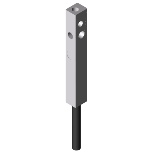
Proximity Switch KLE 6 60x60 - 1NO
Delivery unit
1 pce.
Article-No.
0.0.609.31
Proximity Switch KLE 6 60x60 - 1NC
Delivery unit
1 pce.
Article-No.
0.0.604.41
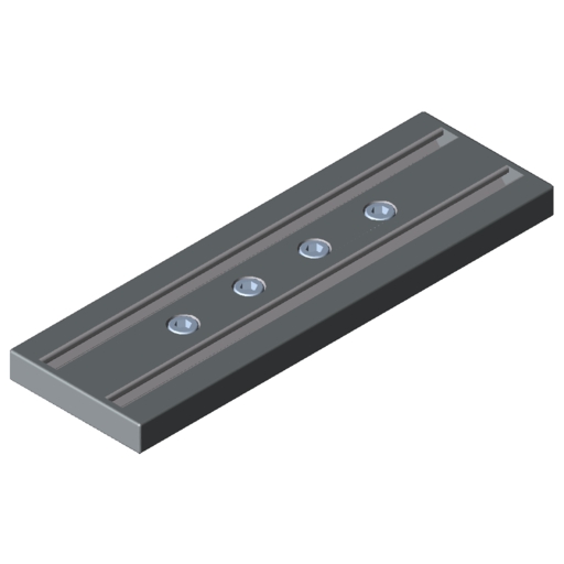
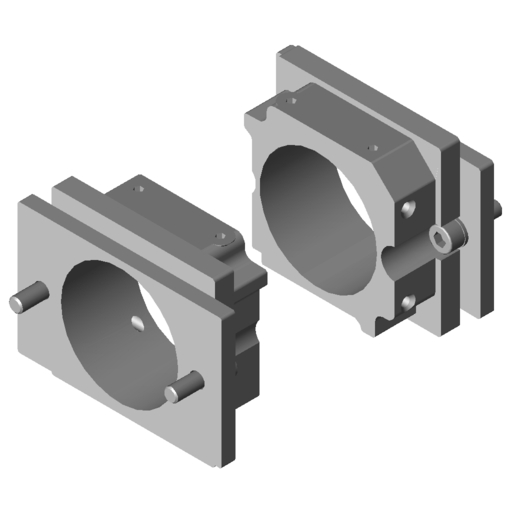
Carriage Plate KLE 6 60x60
Delivery unit
1 set
Article-No.
0.0.609.25
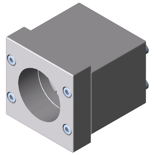
Drive Set KLE 6 60x60
Delivery unit
1 set
Article-No.
0.0.609.80
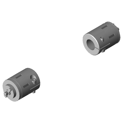
Synchronising Set KLE 6 60x60
Delivery unit
1 set
Article-No.
0.0.609.81
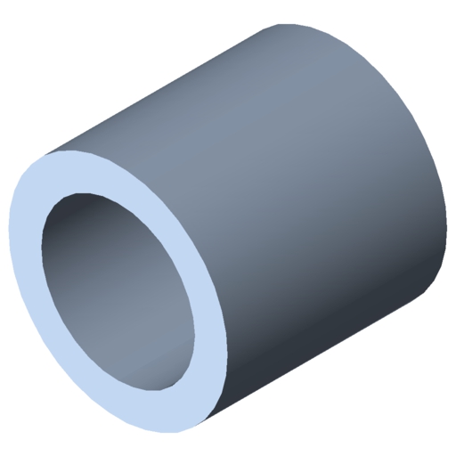
Tube D20x3 St, bright zinc-plated
Delivery unit
cut-off max. 6000 mm
Article-No.
0.0.609.86
Synchroniser Shaft Cover Set KLE 6 60x60
Delivery unit
1 set
Article-No.
0.0.612.46

Downloads

Enquiry form(594 KB)
Assembly instruction(3 MB)

Deflection calculator

To determine the profile deflection around the Y-axis, please enter

The calculation already takes the deflection caused by the dead weight into account.

Load 1

load 1
Deflection f1x: 0 mm Bending stress σ1x: 0 N/mm² Warning! The bending stress exceeds the yield strength of the material.
Deflection f1y: 0 mm Bending stress σ1y: 0 N/mm² Warning! The bending stress exceeds the yield strength of the material.

Load 2

load 2
Deflection f2x: 0 mm Bending stress σ2x: 0 N/mm² Warning! The bending stress exceeds the yield strength of the material.
Deflection f2y incidental: 0 mm Bending stress σ2y: 0 N/mm² Warning! The bending stress exceeds the yield strength of the material.

Load 3

load 3
Deflection f3x: 0 mm Bending stress σ3x: 0 N/mm² Warning! The bending stress exceeds the yield strength of the material.
Deflection f3y incidental: 0 mm Bending stress σ3y: 0 N/mm² Warning! The bending stress exceeds the yield strength of the material.

Applications

Space-saving positioning system - Article EX-01008

This two-axis positioning system takes up very little space.

More information
PDF CAD Parts list

Applications

Machine frame with 3-axis handling - Article EX-01072

This stable machine frame is held together by Angle Brackets and stands firm even when subjected to frequent and rapid movements in three spatial directions.

More information
PDF CAD Parts list Drawing

Applications

3-axis handling - Article EX-01078

item linear technology can be used to design highly accurate 3-axis handling systems. Movement along the X axis is controlled by two synchronised KLE 8. Movement along the Y axis is controlled by roller guide 8 D10 with timing-belt drive, while roller guide 8 D14 with timing-belt drive takes care of the Z axis.

More information
PDF CAD Parts list Drawing
Linear Unit KLE 6 60x60 LR
0.0.605.07

Classifications

Classifications are industry-wide product data standards that are used, among other things, to support structured processing in ERP and e-business systems. Do you need the classification data for all item products for your e-procurement system? If so, please don’t hesitate to contact us.
UNSPSC 7.0
26111506
UNSPSC 9.0
26111506
customs tariff number
84879090